Microchip dsPIC33数字电源IPFC参考设计
Microchip公司的dsPIC33F数字信号控制器(DSC)具有高性能的CPU和丰富的接口,不需要外接芯片就能组成完整的解决方案,采用dsPIC33F内核,3.3V时有40MIPS的性能, 它的DSP引擎支持快速的控制回路,外设如高速PWM,ADC和模拟比较器特别适用于电源转换.本文介绍了dsPIC33F数字信号控制器(DSC)主要性能,方框图以及采用dsPIC33F的交错功率因子修正(IPFC), 两相IPFC方框图, 平均电流模式框图, IPFC MATLAB® 模式框图, IPFC数字控制系统模型框图和IPFC框图, IPFC系统框图和IPFC参考设计详细电路图.Implementing advanced software digital control loops for power applications requires a high-performance DSP engine along with specialized peripherals. The high-performance CPU and rich peripherals of the dsPIC DSC devices enable solutions that do not require much in the way of external support chips. In addition to the space and cost-saving benefits found in the dsPIC DSC solutions, special features enable advanced power conversion. The DSP engine can perform single-cycle MAC with data saturation, zero overhead looping and barrel shifting required to support fast control loop execution.
These devices include peripherals specifically designed for power conversion. Peripherals such as a highspeed PWM, ADC and analog comparators can be tied together using an internal configurable control fabric that enables them to interact directly with one another, resulting in stunning performance gains in digital power applications.
Key Features: dsPIC®33F SMPS and Digital Power Conversion Family
dsPIC33F Core
40 MIPS, 3.3V
Industrial and Extended Temp (125C)
Product Details:
6KB/16KB Flash, 256/1K/2K Bytes RAM
4 to 8 Channel Power Supply ( PS ) PWM
0, 2 or 4 Comparators, 10-bit DAC Reference, 1 DAC out
18, 28 and 44-pin
Pin-compatible, functionally compatible with dsPIC® 30F SMPS & Digital Power Conversion Devices
6.Peripheral pin-mapping for more flexibility/greater usage

图1. dsPIC33F方框图
Interleaved Power Factor Correction (IPFC) Using the dsPIC® DSC
Digital power supplies are used in a wide variety of applications ranging from telecommunication power supplies and base stations to air conditioners and other home appliances. All of these applications predominantly use a Power Factor Correction (PFC) stage to improve the input power factor, voltage regulation and Total Harmonic Distortion (THD) of the input current.
Without such a PFC stage, the current drawn will have significant harmonic contents due to the discontinuous currents drawn over a short duration. This, in turn, will result in increased network losses, radiated emission and total harmonic distortion. At higher power levels, these problems become more pronounced, thereby reducing overall efficiency of the system.
The standard boost converter topology is the preferred method for implementing the digital PFC. It operates the converter in Continuous Conduction Mode (CCM), thereby significantly reducing input current harmonics.
The application note AN1106, “Power Factor Correction in Power Conversion Applications Using the dsPIC® DSC” (DS01106), describes the digital implementation of a single-stage PFC using a dsPIC® Digital Signal Controller (DSC).
This application note focuses on the design of an Interleaved Power Factor Correction (IPFC) converter. It explains the digital implementation of the IPFC on a 16-bit fixed point dsPIC DSC, containing the theoretical aspects of functioning, and MATLAB® modeling. This application note also provides hardware design guidelines and explains how to install and configure the IPFC reference board. The IPFC reference design is intended to aid the user in the rapid evaluation and development of PFC using the dsPIC DSC.
The low-cost and high-performance capabilities of the dsPIC DSC, combined with a wide variety of power electronic peripherals, such as an Analog-to-Digital Converter (ADC), Pulse-Width Modulator (PWM) and Analog Comparator, help to simplify the digital design and development of power-related applications.
Some advantages of using a digital implementation for IPFC are:
• Easy implementation of sophisticated control algorithms
• Flexible software modifications to meet specific customer needs
• Simpler integration with other applications
The controller and hardware design guidelines and techniques described here can be used to create wellformed maintainable applications. The software developed for the IPFC design is highly flexible, so it can be customized and configured to meet the needs of the specific application.
SIGNIFICANCE OF POWER FACTOR
To better understand Power Factor (PF), it is important to know that power has two components:
• Real Power
• Reactive Power
Real Power is the power that is actually consumed and registered on the electric meter at the consumers’ location. It performs the actual work, such as creating heat, light and motion. Real Power is expressed in kW and is registered as kWH on an electric meter.
Reactive Power is required to maintain and sustain the Electromagnetic Field (EMF) associated with the industrial inductive loads. Reactive Power is measured in kVAR.
The total required power capacity including the real and the reactive components is known as Apparent Power, expressed in kilovolt ampere (kVA).
Power Factor is a parameter that gives the amount of real power used by any system in terms of the total apparent power. Power Factor becomes an important measurable quantity because it often results in significant economic savings. Equation 1 defines the Power Factor.

图2.两相IPFC方框图

图3.IPFC的平均电流模式框图

图4.IPFC MATLAB® 模式框图

图5.IPFC数字控制系统模型框图

图6.IPFC系统框图

图7.数字电源IPFC参考设计板外形图

图8.EMI 滤波器电路图

图9.交错式升压转换器电路

图10.MOSFET驱动电路

图11.IPFC参考设计电路图(1)

图12.IPFC参考设计电路图(2)

图13.IPFC参考设计电路图(3)
相关推荐
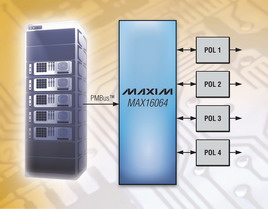
Maxim推出四通道数字电源控制器
2009-11-02
在线研讨会
焦点